A Custom VL6180X
Background
In RoboJackets, our team competes in the RoboCup Small Size League, where autonomous robots play soccer in a fast-paced, strategic environment. One critical subsystem is the breakbeam sensor, used to detect ball possession. The current implementation uses a traditional IR emitter and receiver pair: when the infrared beam is interrupted, it signals that the ball is present.
While this system is simple and fast, it comes with drawbacks. First, it is highly sensitive to alignment—a slight mispositioning of the emitter or receiver can result in unreliable readings. Second, it only provides binary feedback—either the beam is broken or not. This all-or-nothing detection means we have no information about how deep the ball is positioned relative to the robot, which can be important for tasks like dribbling control or validating possession before kicking.
To address these limitations, I proposed using a Time-of-Flight (ToF) sensor—specifically, the VL6180X.
Time Of Flight Sensor
A Time-of-Flight sensor measures distance by emitting a pulse of light (usually in the infrared spectrum) and calculating the time it takes for the reflection to return from an object. This round-trip time is then converted into an accurate distance measurement. ToF sensors provide absolute distance measurements, which makes them much more versatile.
Key advantages:
- Precise distance measurements instead of binary detection.
- Insensitive to minor misalignment due to a wider field of view and reflective nature.
- Compact and self-contained, making integration into small robots straightforward.
I chose the VL6180X, developed by STMicroelectronics, since it is readily avaliable with resources online. Furthermore, it has a built in I2C interface, making it easy to integrate into our robot.
Fabrication
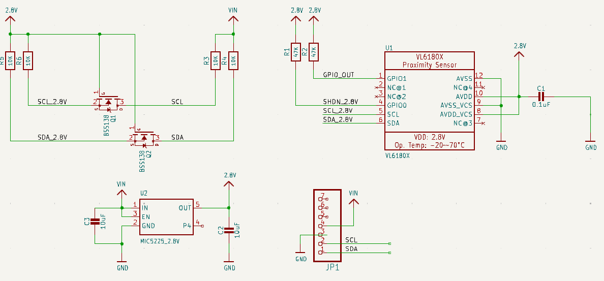
To prototype the custom board, I began by referencing a trusted schematic from Adafruit. Leveraging their proven design ensured that the electrical connections, passive component values, and power conditioning would be functionally sound from the start. However, the origianl Adafruit VL6180X board was far too large to be embedded into our robot's custom dribbling asssembly. To address this, I had to redesign the board footprint entirely from scratch.
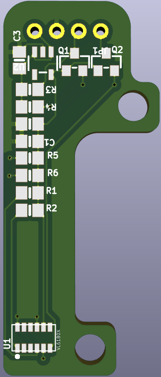
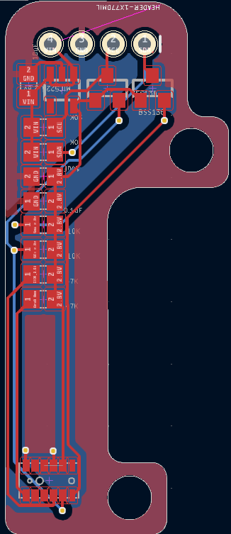
Custom PCB Layout & Design Choices
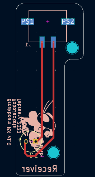
- I started by importing the mechanical edge cuts from our previous breakbeam PCB, which ensured dimensional compatibility with the existing physical structure on the robot.
- After stripping all previous component footprints, I repopulated the board manually using the VL6180X schematic as a reference.
- The VL6180X breakout typically uses a 7-pin header, offering flexibility with GPIO and I2C. Since my application only requires the latter, I reduced the header footprint to a 4-pin configuration. This minimized unnecessary through-holes and further reduced the PCB area.
- I also added ground planes on both layers of the PCB. It was somthing I learnt at the club to simplify wiring and reduce EMI, but also improve signal reliability for high-speed digital lines like I2C.
- Placement of the actual VL6180X sensor was crucial. Fortunately, it was physically smaller than the infrared LED used in the previous breakbeam, making it an easy mechanical replacement.
- With the layout complete, I miniaturized the board even further by removing any unused PCB area.
The Pivot
My original plan was to fabricate the board using the laser cutter at the Hive Makerspace, which allows rapid prototyping on copper-clad substrates. However, the laser cutter was unexpectedly out of service, putting the entire project at risk.
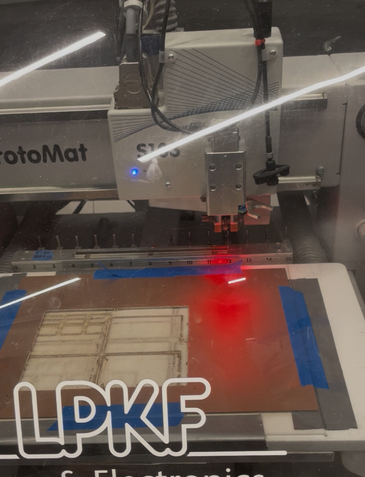
Instead of halting progress, I quickly pivoted to a new fabrication method: PCB milling using the LPKF ProtoMat S103. With guidance from a fellow PI and the machine manual, I learned how to:
- Calibrate and load the machine,
- Secure the copper board,
- Configure the job file, and
- Execute both board isolation routing and hole drilling.
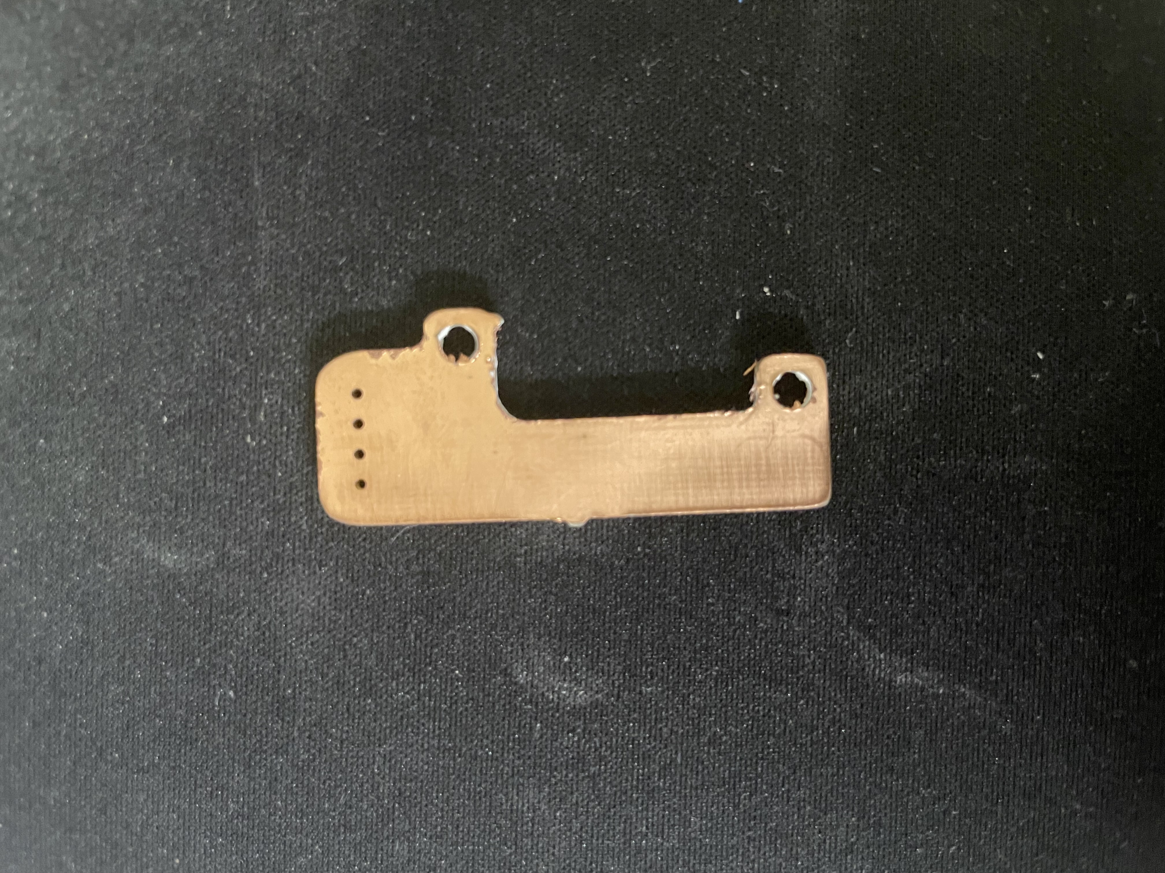
Unfortunately, due to the nature of this process and limitations in available tools, fine copper traces could not be milled—so the final board lacks full electrical functionality. Nonetheless, this prototype represents a major step forward, as the mechanical and outline aspects of the board were validated, and I gained valuable experience with PCB milling workflows.
Result